
First things first:
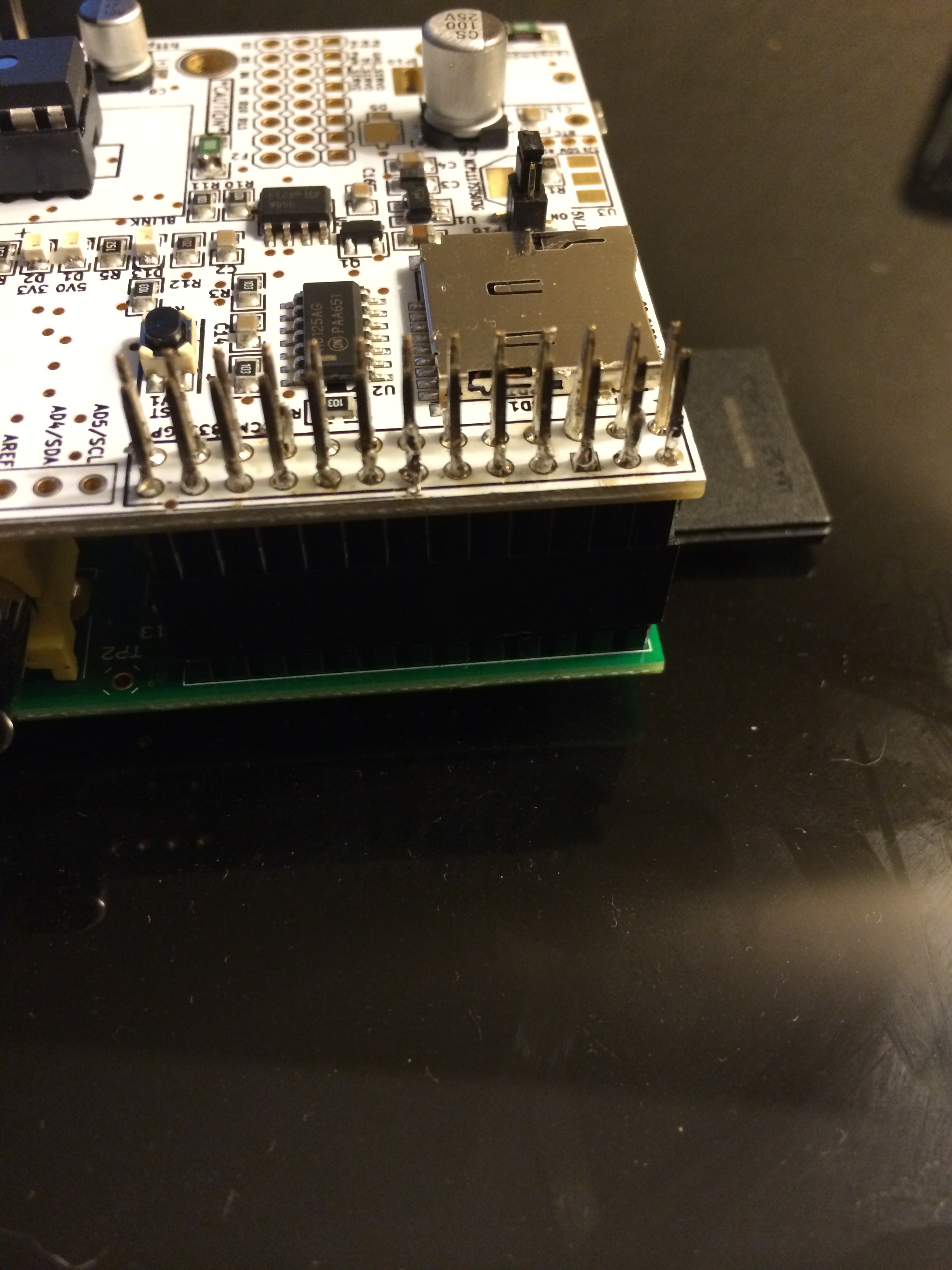
Assemble the head pin to the AlaMode Board(Requires soldering) View Image for visual.
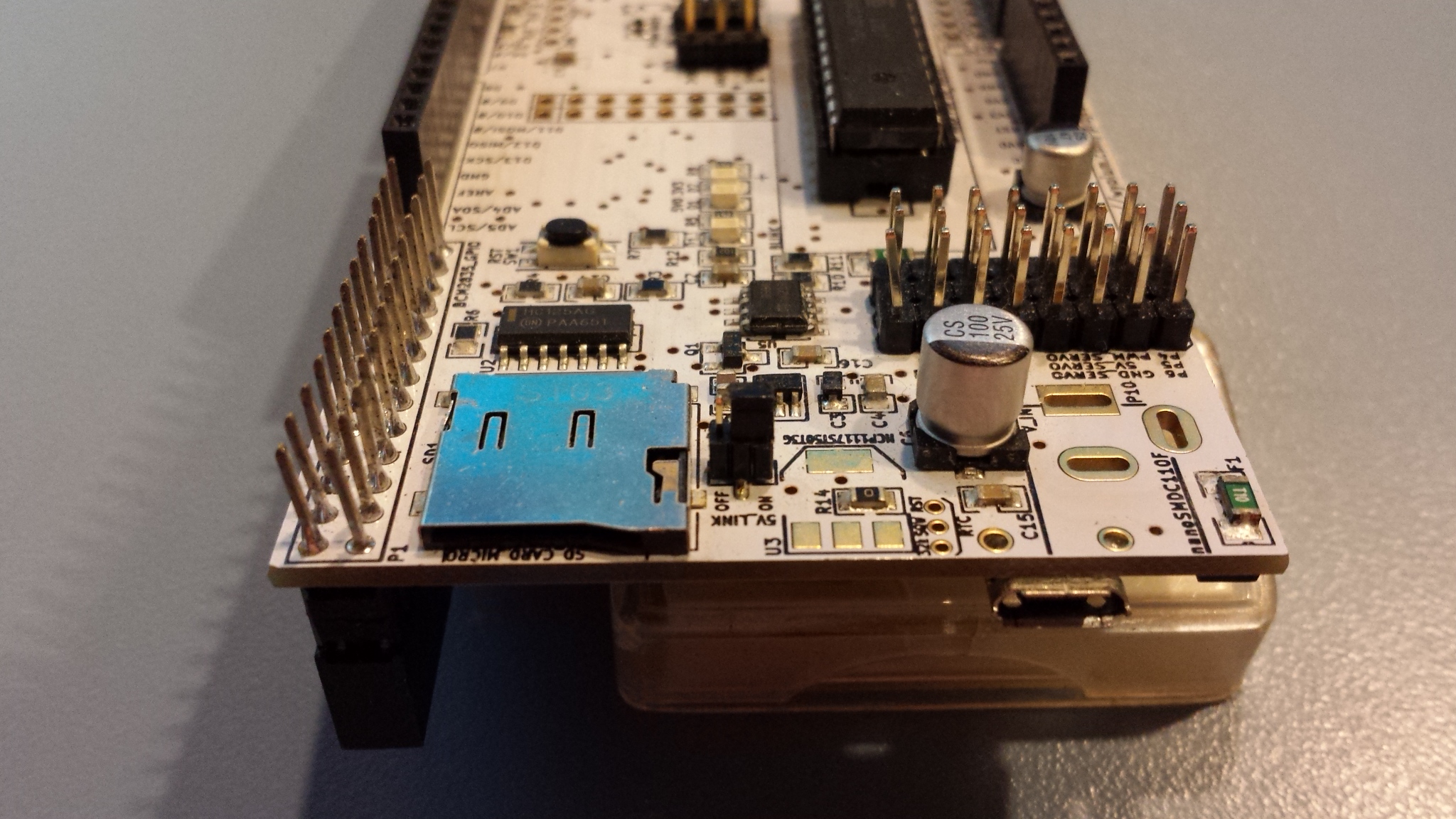 To Power the Alamode and the rPi, set the 5V_link jumper to on. View Image to the Left.
This allows you to connect power to the alamode board
to power both the alamode and the rPi. This is important as the flow meters will draw more power than the rPi can safely supply via GPIO
To connect the flow meter to the alamode:
Pin1(red) -> Ground
Pin2 (middle)-> Any digital pin 2-13. Be sure to set this at the top of the Arduino code
Pin3 -> VIN
Once the alamode has been seated on the rPi (on the gpio pins) and the flow meter has been attached you can power the
rPi up. Plug the power in to the micro usb on the alamode and not the rPi.
Log in to the GUI on the rpi and go to the menu -> Programming -> arduino
This opens a program used to edit the ino file for arduino as well as compiler and uploader.
Click on file -> open
Browse to your raspberrypints directory, look for the arduino -> raspberrypints folder and select the raspberrypints.ino file
At the top of the file locate two lines:
//This line is the number of flow sensors connected.
const uint8_t numSensors = 4;
//This line initializes an array with the pins connected to the flow sensors
uint8_t pulsePin[] = {8,9,10,11};
Change the number of sensors to the total number of flow meters you have in line (in my case I have 4) and set the next one to the pin numbers that the meters are attached to (not the ground or vin). I started at 8 simply because it was easier to attach to these pins. MAKE A NOTE OF THE PINS AND TAPS you will need this information later.
Save the file, do not close.
Go to Tools -> Board and select the Alamode
Go to Tools->Serial and click the box for the serial connection (there should only be one)
In the menu bar there is a button that is a circle with an arrow in it ->
Click that button to compile and upload the ino file to the Alamode board This is important, the alamode needs the code uploaded to it in order to read the flow meters. If you add meters you have to recompile and reupload
Next Edit the /etc/xdg/lxsession/LXDE/autostart file and add the following AFTER the line for the browser
[nbox type=”notice”] @/usr/bin/python /var/www/python/flow_monitor.py[/nbox]
Lets now Reboot the Pi-
Run:
[nbox type=”notice”] sudo reboot [/nbox]
Setting up the tap line-
Once the flow meter is attached to the pi you will need to connect the flow meter inline with your current tap lines. This is where your hose barbs will come in handy, it should look like this:(click the image)
 Then you will splice the tapline and place the flow meter inbetween the splice. Do not add the flow meters at the very end or very beginning of the taplines. Pay attention to the arrow on the flow meter, the beer should flow in the way the arrow points on the flow meter. Now just use some hose clamps and secure it.
Continue to Step 10: RPints Administration.
